Goji Pulper and Double-Stage Refiner
Two connected cylindrical working chambers combine pulping and subsequent refining in one machine family.
GOJI PROCESSING / Buffering
Stainless vessels and connected product pipework decouple uneven preparation from the more continuous treatment duty.
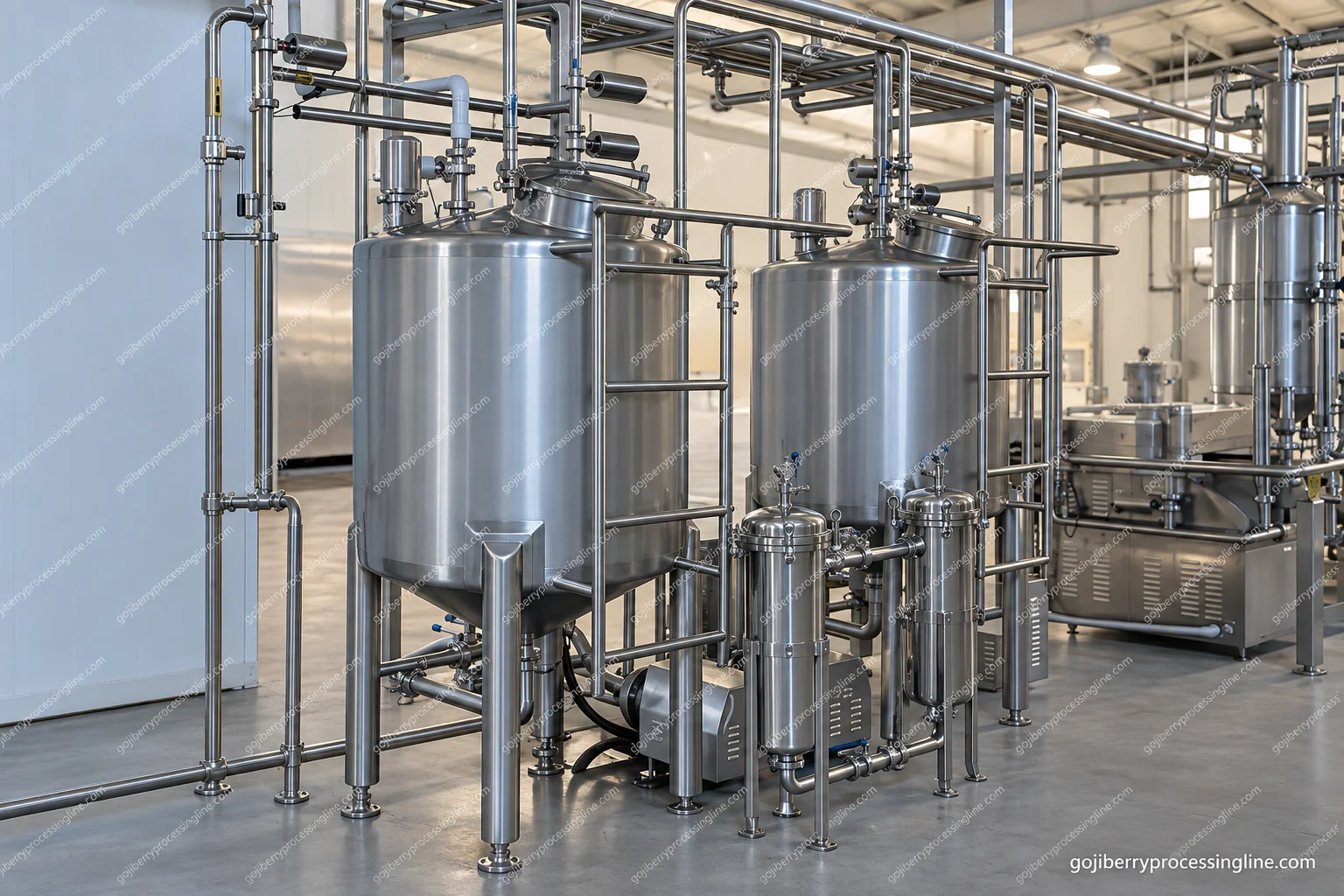
The illustrated vessel group places a short product inventory between upstream processing and downstream demand. Level management prevents a treatment pump from running dry and prevents a full tank from accepting more upstream product. Working inventory, rather than gross tank volume, is the useful quantity for this balance.
Pulp viscosity, fibres, temperature and the pressure needed by the next machine determine the transfer duty. The visible connected pipework establishes the product path; pump selection and seal arrangement are matched to that duty. Do not infer an agitator, jacket or pressure-vessel rating from the exterior of a tank.
Provide access to the outlet, level instruments, vents and cleaning connections. A product return, water flush or diverted product must have an identified destination. The tank should not conceal an uncontrolled mix of starting product, acceptable product and cleaning liquid.
| Assembly shown | Stainless buffer vessels with connected product pipework |
|---|---|
| Useful sizing basis | Working inventory at the planned product flow |
| Transfer inputs | Pulp viscosity/solids, temperature and required discharge pressure |
| Interfaces | Upstream product, level interlocks, pump inlet, drain and cleaning return |
The visible assembly and equipment-family options guide selection; the selected model defines final dimensions, ratings and connections.
Inspect drainability, outlet seals and accessible pipe joints. The internal cleaning method follows vessel fittings and the actual circuit; verify return flow and protect product from residual cleaning liquid. Allow physical access to the pump seal and any vessel fittings.
Use the working inventory at the planned product flow, not the gross tank volume. The buffer must cover the actual interruption pattern between preparation and downstream treatment.
Do not infer those features from the exterior. They must be confirmed from the selected vessel drawing and the product duty.
Only when the vessel fittings and the connected circuit support the chosen cleaning method. Confirm return flow, drainability and separation from production before including it in a CIP circuit.
Tell us the machine, product or starting material. The details can follow.